
Professional PCB restoration techniques from 20+ years of industrial controls experience
When Your Critical Electronics Fail at the Worst Possible Time
Picture this: You’re in the middle of a power outage, your emergency equipment suddenly stops working, and you discover a blown trace on the circuit board. Replacement parts? Not happening for weeks. This is where real-world repair skills separate the prepared from the stranded.
After two decades repairing industrial control systems at companies like Radwell International and Speck Industrial Controls, I’ve learned that when critical equipment fails, you do whatever it takes to get it back online. Here’s the professional trace repair technique that’s saved countless production lines—and can save your emergency equipment too.
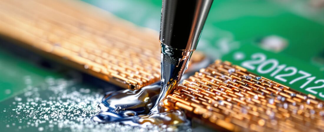
The Desoldering Wick Trace Repair Method
What You’ll Need:
- Desoldering wick (braid) – sized appropriately for your trace width
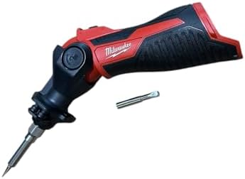
- Soldering iron (temperature-controlled preferred)
- Small screwdriver or similar tool for holding
- Flux paste
- Fine-grit sandpaper or scraping tool
- Multimeter for testing continuity
Step-by-Step Repair Process:
1. Assess the Damage
- Locate the exact break points in the trace
- Check for carbonization or heat damage around the area
- Test continuity with a multimeter to confirm the break
2. Prepare the Repair Area
- Critical step: Carefully scrape off the solder mask coating just before and just after the blown section
- ALL carbonized areas must be removed.
- Clean the exposed copper areas
- Apply a small amount of flux to improve solder adhesion
3. Size Your Desoldering Wick
- Choose wick width that matches or slightly exceeds your trace width
- Cut a piece long enough to span the gap with extra length for anchoring
4. Anchor the First End
- Tin one end of the wick with solder
- Solder this end securely to the prepared trace area before the break
- Ensure good mechanical and electrical connection
5. Bridge the Gap
- Hold the wick in place with a small screwdriver or similar tool
- Key technique: Keep tension on the wick while soldering
- Work your way across the gap, adding solder as you go
- The wick acts as both conductor and mechanical support
6. Complete the Connection
- Solder the far end to the prepared trace area after the break
- Test continuity with your multimeter
- Clean excess flux residue
Advanced Repair: When Damage Goes Beyond Simple Breaks
Sometimes you encounter more severe damage. In industrial settings, I’ve dealt with completely carbonized board sections that required extreme measures:
Carbonized Section Replacement
When heat damage carbonizes the PCB material itself:
- Cut out the damaged section completely with a sharp knife
- Replace with wafer board or similar substrate material
- Rebuild the trace path using the desoldering wick method above
- Seal everything with epoxy for long-term protection and insulation
This isn’t textbook repair—it’s field-proven technique that keeps critical systems running when perfect isn’t possible.
Safety Considerations
Before attempting any PCB repair:
- Power off and disconnect all power sources
- Discharge capacitors safely
- Work in well-ventilated area – flux fumes can be harmful
- Use proper temperature control – too much heat can cause more damage
- Know when to stop – some damage is beyond safe repair
When NOT to attempt this repair:
- Multi-layer boards with internal traces
- Medical or safety-critical equipment
- When proper replacement parts are readily available
Why This Technique Works
The desoldering wick method provides:
- Mechanical strength – the braided copper acts as reinforcement
- Electrical continuity – multiple parallel conductors
- Flexibility – can handle minor board flexing
- Durability – when properly executed, these repairs last years
This isn’t a temporary fix—it’s a professional restoration technique that I’ve used on industrial control systems worth thousands of dollars.
Emergency Applications
This repair technique becomes invaluable during:
- Power outages when electronic equipment fails
- Storm damage to critical emergency gear
- Remote locations where replacement parts aren’t available
- Budget constraints when new boards cost more than the entire device
Your emergency weather radio, power station controller, or communication equipment doesn’t have to become useless because of a single blown trace.
Tools for Your Emergency Repair Kit


Based on years of field repairs, keep these items in your emergency toolkit:
- Temperature-controlled soldering iron (butane-powered or other power options available)
- Assorted desoldering wick sizes
- Flux paste in small containers
- Basic multimeter
- Small screwdrivers and picks
- Fine sandpaper or scraping tools
Professional Results from Field-Proven Methods
After 20+ years of industrial controls work, I can tell you that the difference between a repair that lasts and one that fails again is in the preparation and technique. The methods I’ve shared here aren’t from textbooks—they’re from production floors where downtime costs thousands per hour.
When your emergency equipment fails and replacement isn’t an option, these professional repair techniques can mean the difference between being prepared and being stranded.
Remember: The best repair is prevention through proper surge protection and maintenance, but when prevention fails, having real repair skills keeps you operational when it matters most.
Questions about specific repair scenarios or need guidance on whether a particular board is worth attempting to repair? Contact me at inquire@lucrumlinks.com – drawing from two decades of professional electronics repair experience.