
Ever wondered why some electronic signals look “cleaner” than others? Today, let’s dive into slew rate – a crucial concept in electronics that affects everything from audio quality to digital signal integrity.
Transparency Notice:
At Lucrum Links, we maintain our independence and continue creating in-depth technical content through affiliate partnerships. When you purchase products through our links, we may earn a commission at no extra cost to you. This supports our detailed testing and analysis work, allowing us to keep bringing you honest, engineering-focused reviews backed by decades of electronics and technical experience.
The Mystery of the ‘Working’ Encoder
Picture this: I’m working on an encoder repair, confronted with a classic challenge—a blackened integrated circuit (IC) with unreadable markings. As any experienced engineer would do, I identified it as an 8-pin op-amp and replaced it with a compatible substitute. Basic testing showed everything working perfectly. Case closed, right?
When ‘Working’ Isn’t Really
Unfortunately, my initial assessment of the encoder’s operation was misleading. The replaced IC passed all preliminary tests, giving me a false sense of security. However, after extensive usage, intermittent failures began to surface. The encoder would occasionally drop signals, leading to erratic performance. This was a stark reminder that just because a system appears functional does not mean it operates under all conditions or matches the original specifications.
The Lesson on Slew Rates
This experience compelled me to delve deeper into the specifications of the components we use. One crucial aspect that was overlooked was the slew rate. The slew rate measures how quickly an IC can output voltage changes, and it can significantly impact performance in many applications. I had used a substitute that matched the voltage rating and pin configuration but had a notably slower slew rate. This discrepancy wasn’t evident in initial tests with static signals but became apparent under full operational conditions.
As I delved further into troubleshooting, I realized the encoder’s work depended on rapid signal transitions. A slower slew rate failed to keep up with the required signal dynamics, causing random data drops. This incident highlights a hidden trap—initial compatibility is not solely about pin configuration or voltage ratings; quiet factors such as slew rate may have major implications for long-term reliability.
In conclusion, this humbling experience serves as a critical reminder for engineers. Always verify the full specification sheet of any replacement component, especially where high-frequency signals are concerned. The lesson learned here is about diligence. When in doubt, dig deeper; your next repair could save you a world of troubleshooting down the line. Remember, just because something seems similar doesn’t mean it is similar enough. The success of your fixes relies on your knowledge and understanding of all relevant characteristics.add
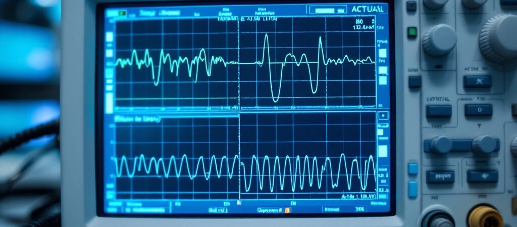
If you are curious the actual scope I used to find the problem is still listed, although I am sure it’s different model slightly by now. You don’t need to spend that much if you are starting out by the way but what matters is that it is high impedence and that it’s , well I would say at least 100 MHz Sample rate.

- Hand-held dual channel oscilloscope, and recorder
- 20 MHz oscilloscope bandwidth
- Two 5,000-count true-rms digital